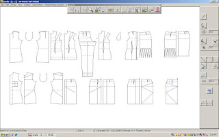
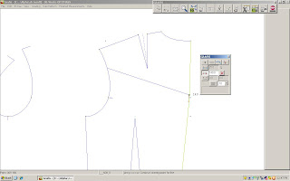
Just as I have folders, boxes and rails of paper and cardboard pattern pieces so are the patterns in Grafis multiplying, so it is important to adopt a good filing method from the get go. The data structure of Grafis is a divided into two areas, one which is administrated by you and one that is administered internally by Grafis. Administered in dialog with you are the Collection Folders, and within those the individual styles. Within the Style the parts (pattern pieces) can be as many as 500 per style, and are named partly by you and given a 3-digit number by Grafis, within each part the information pertaining to Construction record, Points, Lines, Text, Hatching and further Technological information is stored. The pattern piece/part must be named accurately and clearly identify what it is, as it is used in the automatic text function to label the pattern piece on completion.
Grafis records every construction step, I have found this very useful in resetting an exercise to the beginning to repeat and learn other methods or interactive ways of pattern making. For example I want to put a vent into the side seams of a skirt, put 8 buttons down the centre front with an overlap of 40mm for the button stand. I call a basic block, Skirt 20, make changes with Options to make a Straight Skirt and Display measurements. I then trace off the front and back parts into Part Organisation using Insert and then start on the vent construction and the button stand. At this point in the exercise I take note of the construction steps and click on Test Run, so if I make mistakes during the exercise I can easily reset the steps and begin again. We have also been shown to step through a construction step-by-step by clicking Test Run and S-key together, pressing S-key again to quit. In my opinion, it is important to plan your pattern making and have a clear overview of your construction steps before you begin, to take pencil and paper map it out first so you know where you are going, and what the expected outcome will be.
Corner Menu
When I lived in Sweden, the first thing I learnt was ‘The Right Hand Rule’, to cross the road and to drive on the right side of the road. This same principle is used in the tools of Grafis. In Grafis the line receives direction and the cursor indicates which direction you must travel along the line in, by imagining that you are driving on a road in right hand traffic the line to be clicked is the central island in the road.
Link Tool Menu
Sing or Rap, “X to the left! Y to the Sky!” Grafis uses x-axis and y-axis coordinate system, so very similar to other layout software. With the angle definition beginning from the positive X axis, therefore a positive angle rotation moves anti-clockwise and a negative angle rotation moves clockwise.
It ‘s fun to learn new tools, the Deleting menu found via Basic menu hosts a variety of deleting options from points and lines to the contents of a rectangle clicked and dragged over what you want to delete. To create Parallel lines, there is a choice of fixed distance or putting in your own value which must be specified first, there is also the interactive Parallel 10 Tool which is selected first and then the parameters are adjusted.
Parallel Tool Menu
The simple use of the Corner in the Corner menu is a good starting point to practice the right hand principle and to create corners on seam allowances. There are 10 interactive corner options, from Corner 40 with the option of a Curve, Circle and Line. Or the following 7 options for Mirror Corner 10, Mitred Corner 20, Vent Corner 30, Co-ordinated Corner 50, Angle Corner 60, Co-o. angle Corner 70, and finally Hem Corner 80. Go and play with Corners!!
Co-ordinated Corner
The last few lectures have been made up of mastering the easy line functions and really learning these tools. We have covered Linking Lines, Raster, Lengthening and Shortening Lines, Cut, ‘Cut on’ and Separate, as well as the tool - Front Edge 30.
Grafis Support Programs - Front Edge 30
Basically, Linking lines allows 2 separate lines to be joined, click on deposit to complete the link operation. Lines can be linked in a single or chain; Chain is all tangent (meaning going off on all directions, not to dissimilar to my posts) lines are automatically joined and single is a simpler option, manually select lines and link them. Link with a curve; links 2 lines with a curve between 2 points, it’s used for hemlines, side seams, darts, godets etc. To determine the curve click on the line following the right hand principle at the beginning and end points, only adjust at these fixed points. Curves created with Link 10 Tool can be adjusted more easily, there is a short video demo under the Question Mark ? button for this tool.
Points of the interactive curve follow priorities, so always start adjusting the objects with the highest priority. 1st move Base point – a red dot at the beginning and end of the curve. 2nd move/ adjust Direction handles – shown with a small angle icon at the end of a dotted line. 3rd and 4th shape points are between the 1st base points and are shown with smaller dots, the 3rd shape point being normally situated at 50% or 0mm of the curve. (Some things are better described in a diagram, points being one of them).
Moving swiftly onto Raster: Raster are the points on a line, dividing the line into sections, the Raster menu offers 4 functions: 0-1-2-4 and an interactive tool Raster 10 tool.
Raster Menu
Raster 0: on a straight line the beginning point and the end point.
Convert to line: resets the sequence of points back to a line.
Raster 1: adds a given number of points to a line an equi-distance apart, including the start and end point. Activate by clicking, then select ‘+/- copy’, set number of points in menu then click required line to be rastered (or in simple terms ‘dotted’).
‘+/- copy’ Appears in many functions; it determines whether a given operation will replace the chosen line, or will be an addition to it. + copy – both line and point sequence are existent, - copy – only point sequence is existent.
Raster 2: points with pre-set distance value are constructed along a line. The pre-set value is an approximation as Grafis corrects the distance and all points including the start and end, divided have the same length/distance.
Raster 4: distributes a number of points between 2 constructed points. To do this, enter number of points into menu, then click line to be rastered, for start and end point a sub-menu appears.
Raster 10 tool: can be adjusted regarding position and number of points, makes buttons a breeze! Click the tool and select the line that the points are to be spaced along. Double click on the new point sequence and adjust using the follow, 1. distance to base line, (length) 2. number of points or buttons, 3. start of point sequence from beginning of the line, 4. depending on option: point distance or last point distance to base/hem line, 5. angle to base line.
Cut, Cut on, Separate lines… separate lines, divides a line into 2. It is defined in 3 ways, i. Separate or cut at a cutting line; Separate in a corner; Separate or cut freehand by eye. Cut – shortens or lengthens a line up to the intersection, click part of the line you wish to keep and follow the right hand principle. Lengthening is called ‘cutting on’ and is possible to 500mm!
Point, Line and Direction Constructions, and Raster
The Tool Front Edge 30 creates necklines suitable for high collars and revers collar construction, button stand, with open neckline options and front edge hem designs. All front edge tool variations require 3 or 4 lines, namely; the neckline; centre front in a continuous line, hemline and a reference point for the revers (which is the breakpoint on a collar construction, a point somewhere on centre front). The tool is found in the call list Grafis Support Programs.
Co-ordinated Angle Corner 70 Tool
Exercise using Jacket front with princess seam using interactive options: front Part 30, parallel for adding seam allowances and hem and finishing with co-ordinated angle corner 70.
I really enjoy working in this program and learning it, these are my own student notes and are not an educational substitute, some of the information might infact be misleading. As I mentioned in previous ramblings, Grafis is very generous with their educational material and free educational download version of the software. Go ahead and challenge yourself to learn it!
More Point Line and Direction Parts
Straight Skirt Grade - point exercise
Using Partial Length to create a back yoke style line


